Magnetic fields are measured in Tesla - 1 T field exists when 1 meter of wire carrying 1
amp of current experiences 1 N of magnetism force.
B fields into the plane of the paper
are represented by X
B fields out of the plane of the paper are represented by .
moving charges experience magnetic forces
F = q v B^ = q v B sin q
RHR - thumb points in direction of the positive particle's velocity, fingers in the
direction of B^,
and palm in the direction of the force
FB = FC that is, moving charges are
forced into circular paths while traveling through magnetic fields - paths are usually
described as cw or ccw
q v B^ = m ( v ² / r )
the time required for one revolution in these circular paths is independent of the
particle's velocity
v = (2 p r) / T
the radius of the particle's circular path is directly proportional to the particles
mv, and inversely proportional to the particle's charge and the strength of the magnetic
field
both stationary and moving charges experience electric field forces
F = qE where E = V / d and can be measured in either N/C or V/m
particles are linearly accelerated through electric fields - "accelerating
potential"
| q V | = ½ mvf² - ½ mvo²
velocity selectors are designed to permit similarly charged particles with an
predetermined velocity travel in straight paths through crossed magnetic and electric
fields
FB = FE
q v B^ = q E
v = E / B^
field lines run out of the N pole and into the S pole
like poles repel, unlike poles attract (similar to field diagrams for two point charges)
solenoids are electromagnets - Curl Rule - fingers curl in the direction of the current
flowing through the coils, thumb points in the direction of the solenoids N pole (magnetic
moment)
solenoids are important because they have uniform B fields along their axis
B = mo n I where mo = 4 p x 10-7 Tm/A and n = N / L
current carrying wires produce radial B fields
curl rule - thumb points along the wire in the direction of the current, fingers curl
in the direction of the B field
B^ = 2 x 10⁻⁷ I / d
magnetic fields from neighboring wires can be superpositioned to find the net B
in a region of a plane
current carrying wires experience forces when placed in external magnetic fields
F = B^ external I L
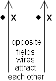
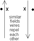
parallel wires carrying opposing currents repel
parallel wires carrying currents flowing in the same direction attract


galvanometers - sensitive current carrying coils rated for a maximum allowed current
and voltage to produce a full scale deflection.
ammeter - place a low resistance shunt in parallel with the galvanometer as a path for
the excess current
I main = I galvanometer + I shunt
shunt and galvanometer have the same voltage
remember that ammeters are USED in series to determine the current passing through a given
resistor
voltmeter - place a high resistance multiplier in series with the galvanometer to bleed
off the excess voltage
V total = V galvanometer + V multiplier
multiplier and galvanometer have the same current
remember that voltmeters are USED in parallel to determine the potential (voltage) lost
across a given resistor
The formula used to calculate the number of magnetic flux (field) lines which pass
through a given cross-sectional area is
F = B^ A
F is measured in webers, B^ is in T, A is in
m²
Note that these units define a Tesla as a weber/m².
When the number of flux lines is constant, no emf is induced in a coil. When you change
the number of lines, an emf is generated in the coil opposing THE CHANGE.
Faraday's (Lenz) Law of Induction is E = - N (D
F /Dt )
The expression D F /Dt = D (B^ A) / Dt is merely an abbreviation for the rate of change of flux lines.
Notice, an emf is induced only when the number of flux lines passing through an enclosed
area changes. This number can be changed by either changing the strength of the
magnetic field OR by changing the area of the coil.
E = - N B^ (D A /D t ) = - N B^ (A f – A o )/t
E = - N A (D B^
/D t ) = - N A (B^f
– B^o )/t
Also notice that the emf is induced to oppose these changes (designated by the negative
sign). Your right-hand curl rule (your fingers will curl in the direction of the induced
current when your thumb points in the direction of the coil’s induced magnetic moment
or North Pole) is used to determine the direction of the induced emf/current.
The formula used to calculate the emf induced in a loop which has a changing
cross-sectional area while present in a constant perpendicularly-oriented magnetic field,
B^, is
Emotional = - N B^ v l
This occurs when a loop is pushed into or pulled out of a constant magnetic field
or when a sliding conducting bar changed the enclosed area within a magnetic field. The
right-hand curl rule was used to determine the direction of the induced emf/current.
The force that must be applied to maintain a constant velocity is calculated with the
equation
Fright = B^IL
= B^ (E /
R) L
= B^ (B^
v LR) L
= B^² v L ² R
The generalized equation for the operation of a motor is Electricity + Magnetism
= Motion
When electricity is supplied to a coil and it is inserted within a permanent magnetic
field, the two magnetic fields repel and attract each other causing the loop to rotate.
The generalized equation for a generator is Motion + Magnetism = Electricity
When a coil is rotated within a permanent external magnetic field, the changing flux
lines generate a voltage within the coil. Since the coil has resistance, this induced emf
will result in an induced electric current. The equation for the AC voltage generated in
the coil is v = Vo sin (2pf)t where
Vo = NBA(2pf) and the frequency is
in hz.
The Law of Transformers states that Ns / Np = Es
/ Ep where Np and Ns are the number of loops in the
primary and secondary coils and Ep and Es are the emfs in the
primary and secondary. A transformer only works when the number of flux lines through the
iron core of the transformer keeps changing - therefore, the primary must be connected to
an AC source. Any change in flux in the primary is communicated to the secondary through
the iron core. The power utilized in both coils is the same!